
disguise insights - 3D workflows
FACE for professionals
FACE for MI Resellers
FACE Project Integration
Written by Joe Bleasdale, Associate Product Manager
Why a 3D workflow?
disguise features a 3D real-time simulator for visualising venues and video displays including LED panels, projection surfaces, DMX fixtures, or any other video display technology. To simulate a pixel-perfect screen which is complex in shape, for example a building or a car, a fundamental understanding of 3D modelling and UV mapping techniques is required.
UV mapping is the process of generating a 2D representation of a 3D object. This 2D representation is constructed from UV coordinateswhich are commonly known as ‘texture coordinates’. U represents the horizontal axis and V represents the vertical axis. Each UV coordinate has a corresponding point in 3D space called a vertice. Together the vertices form edges, edges form faces, faces form polygons, and polygons form surfaces.
A UV map can be generated automatically by a 3D application, for example 3ds Max, Maya, Cinema 4D and Blender, but normally the UV map requires editing manually. It is possible to tell if a 3D object file (.obj) has a UV map or not by opening it as a text file. If an object has a UV map, it will have UV coordinates, and if there is no UV map then it doesn’t.
A UV map tells the media server how to translate back and forth between the 2D source content and the mesh's 3D polygons for visualisation and to enable 3D content mapping and projection mapping capabilities.
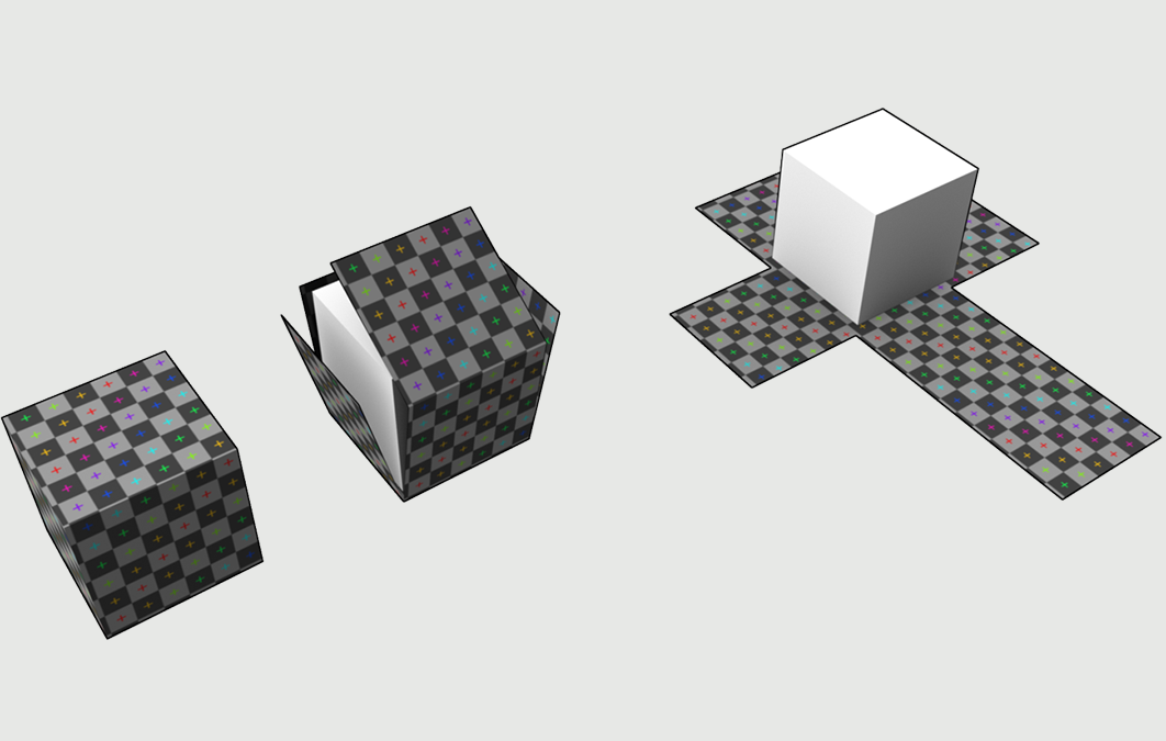
A UV map doesn’t specify the aspect ratio or resolution of the mesh. UVs are defined in what is called 'normalised coordinates', which means they must have values between 0 and 1 on both the U and V axes, and there shouldn’t be any gaps left at the edges of the UV 'box'.
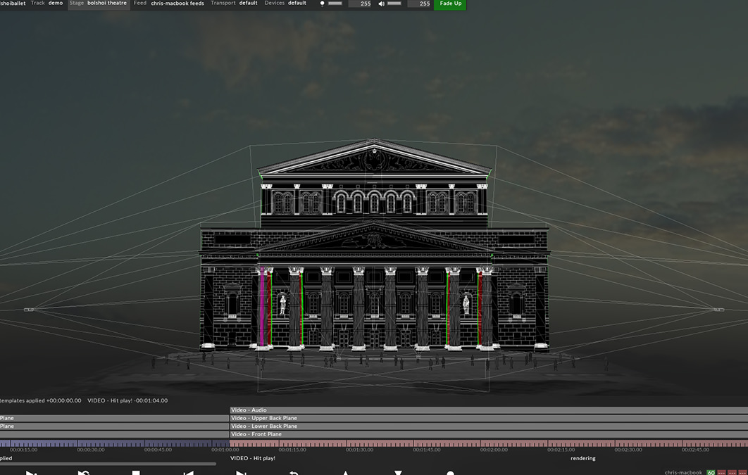
This enables users to select the appropriate resolution and aspect ratio based on artistic and technical requirements from within the disguise visualiser. The UV map determines the output to the connected display devices, however preparing UV maps for projection surfaces requires a slightly different workflow.
Normally the projection surface is unwrapped into a texture that the content creator can generate video content from, in a similar way to how artists texture 3D models in the video games industry. UV maps can be rendered into a content template and placed as a background in Adobe Photoshop, Illustrator, After Effects or any other image/video editing application, with the resolution being calculated from two variables: aspect and density.
To learn more about 3D workflows and UV maps in disguise, visit our online user guide:
Find out more about UV mapping
Find out more about 3D workflows